Hub Cable Replacement

What you can expect to find on this page

The process of replacing a worn or broken hub cable is explained below.

Axlering types

The method of replacement for a worn or broken hub cable can be carried out differently depending on which axle-ring type is mounted.

One-piece axle-ring with pressed-in cable guides

The one-piece axle-ring was mounted on all internal gear mech versions until the beginning of 2003 (until Serial Number 25300). This type of Axle-ring is secured to the gearbox with six axleplate screws. The cable guides of the one-piece axle-ring remain fixed to the axle-ring. This can be seen once the axleplate has been removed. To replace the hub cable, the axle-ring complete with the cable pulley must be removed (use spare part = ‘Hub cables’ Art. #8271).

Replacement procedure Shown here

Quick-change axle-ring with cable guides seated within nylon cylinders

The quick-change axle-ring is secured to the gear box with five axleplate screws. The axle-ring remains secured to the gearbox with one more screw and the cable guides seated within black nylon cylinders rest in the axle-ring. This can be seen once the axleplate has been removed. When replacing the hub cable, the axle-ring remains attached to the SPEEDHUB.

Replacement procedure see Quick-change axle-ring

Pointer

When correctly mounted, the hub cable should last a good 10,000km. Should the cable get damaged and need to be replaced sooner, the reason for this damage should be identified and corrected before mounting a new hub cable. Possible reasons:

  1. False alignment of the axle plate or the cable guide can result in the cable rubbing against the metal of the cable adjusters/guides. (see chapter Axleplate alignment).
  2. Torque not properly secured. The hub axle rotated and streched the cables to breaking Point.
  3. Other physical damage (eg. crashes, accidents).

Mounting Guide Video

Quick-change Axle-ring

A Hub Cable Easy Set (Art. #8573) is available for a quick replacement. A Hub Cable including all needed parts can simply be slotted into the axle-ring as a complete unit (see included instruction sheet for mounting instructions). To spare parts in the shop.

Remove the rear wheel. With good wire cutters cut off the four cable ties that hold the concertina tubes over the hub cables.
 

Unscrew the bayonet male connectors from the hub cables (M4x4 - 2mm Allen wrench) and then remove the concertina tubes.
 

To change the hub cables the axle plate must be firstly removed. To do this, unscrew the five axle plate screws (M4x25 - Torx TX20).

Attention

Take note of the position of the axleplate against the hub cable guides for correct refitment later.

The axle-ring remains attached to the axle by one more countersunk head bolt underneath the axleplate. Lie the wheel on a worktop with the axle-ring facing upwards. Remove the two cable guides with the nylon cylinders and the cable pulley by rocking the cable guides from side to side until they are released from their seats within the axle-ring.


Attention

Do not lie the wheel on the axle ring side, as it is possible that oil could leak out of the bolt holes.

The mounting of the cable pulley must be carried out in gear #14. To do this, the axle has to be held steady with a 17mm wrench on the locking nut on the sprocket side.

With an 8mm wrench turn the hexagonal peg in an anticlockwise direction until the end stop. Now the hub is in gear #14.

Remove the old hub cable from the cable pulley. Clean and deburr cable pulley if necessary. Insert the new hub cable (0.9mm) approx. half way into the cable pulleys lower hole from the inner side.

Next push the other end of the cable into the top hole of the cable pulley until both ends of the cable stick approx. the same length out of the other side.

Hold the cable pulley tightly and with the other hand grasp the 0.9mm hub cables and pull them quickly until the cable sits properly in the cable pulley without getting kinked.

Pay attention to which side of the cable pulley is the mounting side. The back/mounting side has a recess before its hexagonal hole. The front side is without this recess.

Bend the hub cables in the direction of the cable runs in the cable pulley (this is easily achieved by placing the cable pulley onto an 8mm allen key). The top cable should be wound approx. 2¼ times around the pulley. The bottom cable approx. 1/2 of a turn in the opposite direction.

The picture shows the cable pulley with the correctly wound hub cables. The cable runs are completely filled with the gear cable and the groove faces toward the 10 o´clock position.

The cable pulley should be placed over the hexagonal peg of the shifting shaft with the groove facing towards the countersunk axle bolt (or as near to it as possible approx. 9-10 o'clock Position). Both Ends of the hub cable should be placed through the seats of the cable guides.

Place the cable guides over the hub cables, nylon cylinder end first!

The cable guides are sitting properly in their seats of the axle-ring when the rounded top of the nylon cylinder is facing upwards (as shown in the above picture).
 

Press the nylon cylinders firmly into their seats of the axle-ring.
 

Apply a little grease between the axle-ring and the cable pulley. Remount the axleplate checking that it is at the same angle against the cables guides as it was before. Tighten up the five countersunk bolts (Torx TX20 - tightening torque:  3Nm/25”lbs.).
 

Check the rear side cable is pulled out to its end stop. Measure this cable and cut it at 165mm with sharp wire cutters (see Tip). Place a new concertina tube carefully over the cable and place the male bayonet connector onto the end of the cable.

Push the cable up into the male bayonet connector as far as it will go and tighten the two 4mm headless screws with a 2mm allen key (tightening torque 1.5Nm/12”lbs.). Pull the  side cable with pliers through the 13 clicks of the gearbox until the end stop (gear #1). Measure* this cable and cut it at 165mm with sharp wire cutters.

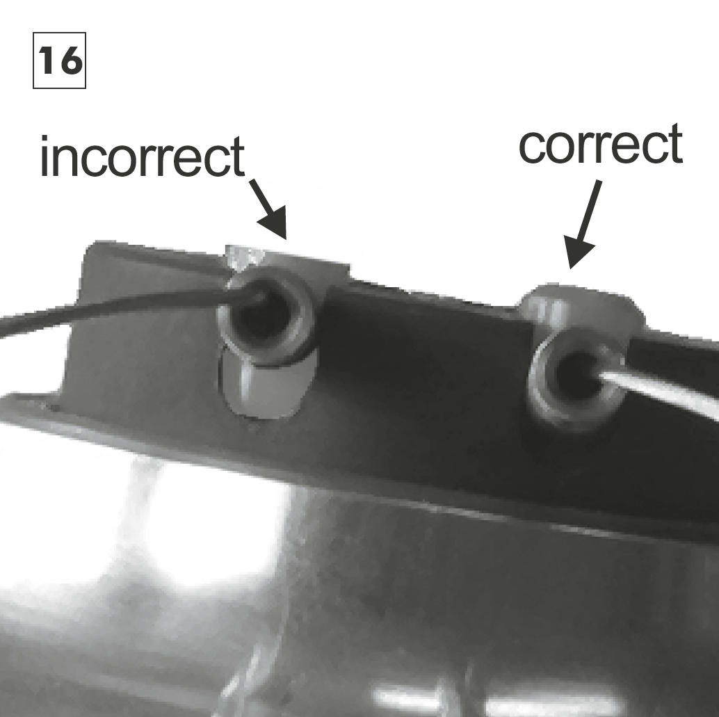
Place a new concertina tube and male bayonet connector over the cable. Tighten up the connector as with the other. Pull the shorter cable until both of the hub cables are approx. the same length. Place the two new concertina tubes over the cable guides and secure them with cable ties. Make sure that the cable ties clamp the concertina tubes over the recess in each of the cable guides.


The top ends of the concertina tubes must be placed over the ends of the male bayonet connectors and secured with cable ties. Make sure that the cable ties clamp the concertina tubes over the recesses.

Tip

* For easier measurement of the correct cable length the special measuring pipe (Art. #8711) can be ordered. Simply place the measuring pipe as far down as possible over the cable. Cut the cable at the end of this pipe, then slide the new concertina tube over the pipe. Remove the measuring pipe, secure the male connector and the concertina tube in the correct positions.