What you can expect to find on this page
The process of converting an internal gear mech to an external gear mech is described below.
Advantages of the external gear mech compared to the internal version: the shifter cables run uninterrupted from twist shifter to cable box, so the need for a separate cable stop is eliminated. Another advantage is that regular internal shifter cables (1.1mm stainless steel), can be used, which are available in bicycle shops all around the world.
Video workshop
Disassembly of the axle-ring
One-piece axle-ring
The one-piece axle-ring was mounted on all internal gear mech versions until the beginning of 2003 (up to serial number 25300). This type of axle-ring is secured to the gear-unit with six axleplate screws. The cable guides of the one-piece axle-ring remain fixed to the axle-ring. This can be seen once the axleplate has been removed.


Quick-change axle-ring


Procedure after removing the axle-ring


Mounting the external gear mech


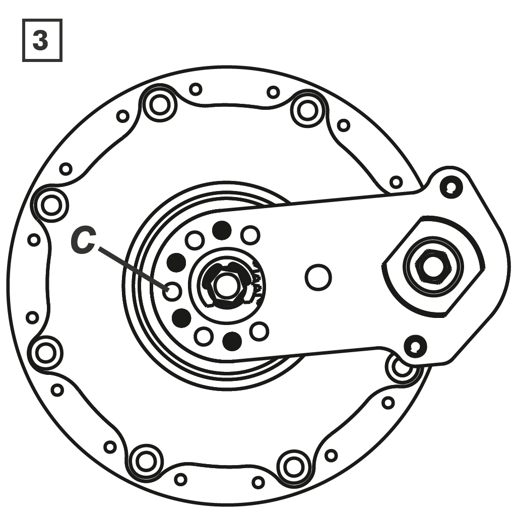
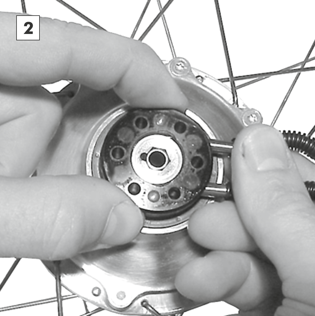
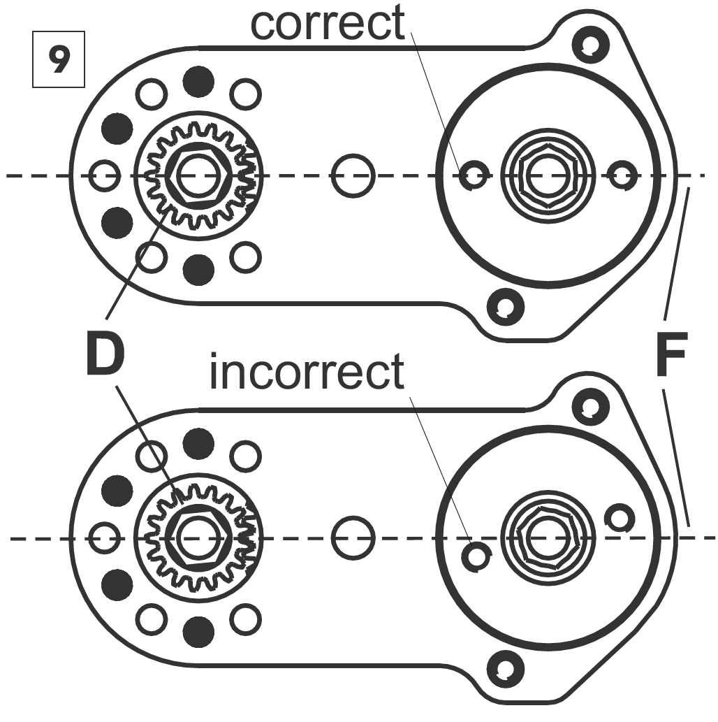
Insert cog D over the hexagonal peg E with the toothing facing outward. There is one mounting position out of the possible six, where the teeth of the cog D and the sprocket C line up. In this position the screw holes of the cable pulley remain as close as possible along the center line F. This position is the correct position. It may be neccessary to turn the cable pulley lightly to the left or right to allow for an easier assembly.
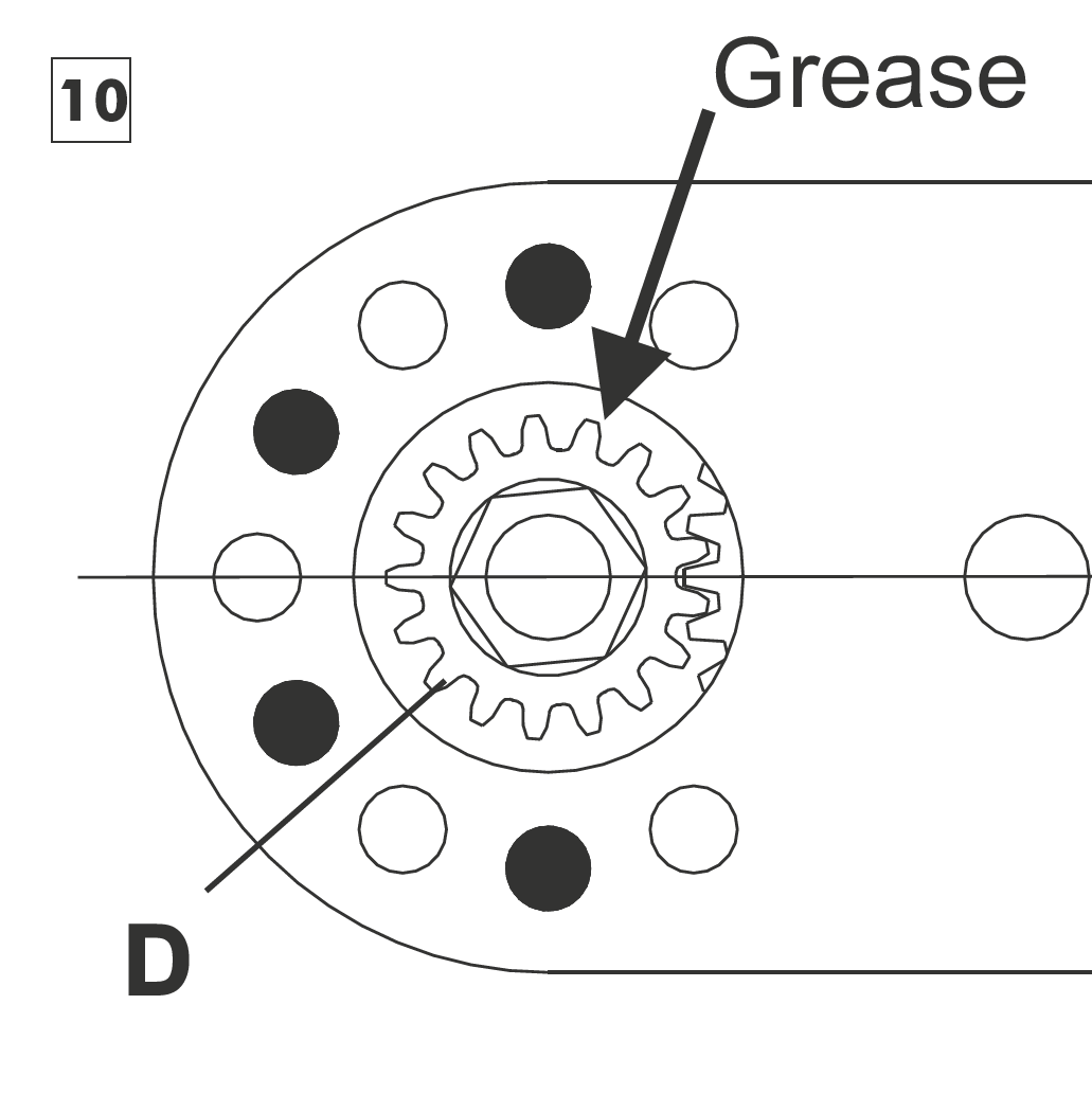
Apply a small amount of grease between the cog D and the external transfer box. Remount the axleplate and secure it in the correct position with the five axleplate screws (M4x25 - Torx TX20, tightening torque 3Nm/25” lbs.).
Further steps for mounting the external gear mech can be found in chapter external gear mech.


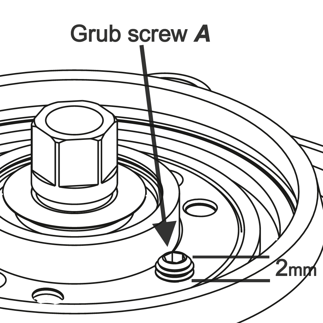
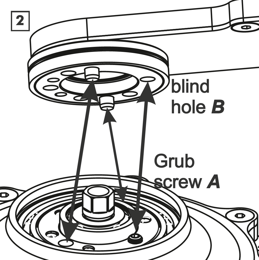
Grub screw of the External Gear Mech
All gear hubs built after Serial Number 47000 and equipped with an external gear mech have an M4x8 grub screw mounted into the sixth threaded hole of the axle (it helps to prevent potential oil leaks). Therefore, the external gear mech can only be properly fitted in one position (PFig. 2) over the axle.