What you can expect to find on this page
Wheels with the Rohloff SPEEDHUB 500/14 are generally far stronger than derailleur wheels. A correctly laced 32 spoke SPEEDHUB wheel is usually equally as strong as a 48 spoke derailleur tandem wheel. The spokes are arranged symmetrically so each spoke can be tensioned evenly. The increased wheel stability becomes immediately apparent after riding just a few meters.
The process below shows you one method of correctly lacing a SPEEDHUB wheel.
Wheel lacing
The number of times that the spokes are crossed over depends entirely upon the size of the rim.
All rims larger than 24" in diameter must be laced in a two cross pattern.
All 24" and smaller sized wheels must be laced up in a one cross pattern.
Due to the high torsional strength of the hub casing, the use of a reversed lacing pattern on the brake disk side (DB versions) is not necessary.

Rims are manufacturered in diferent ways. The type of nipple hole pattern must be determined before lacing the wheel as this will require a different lacing method to be followed. In picture 1 the European nipple hole pattern (EU) is shown. The first spoke hole behind the valve hole lies to the direction of the left hand hub flange (pay attention to the rotational direction of the rim).

In picture 2 the French nipple hole pattern (FR) is shown. The first spoke hole behind the valve hole lies to the direction of the right hand hub flange (pay attention to the rotational direction of the rim).
If the spoke holes of the rim are all centrally drilled, then the lacing method for a European nipple hole pattern should be followed (see appendix).


Wheel lacing methods
Rims with French spoke-hole pattern


Three holes (one hole) behind this first spoke is where the trailing spoke should be inserted, this spoke is to be inserted from the outside of the hub flange (spoke head facing outwards). This spoke is to be crossed over the first spoke and inserted into the nipple hole of the rim that is two holes before that of the first spoke.

The next trailing and leading spokes are laced into the rim in exactly the same way. The only difference being that they enter the hub flange two holes away from the last respective leading or trailing spoke, and that they enter the rim four holes away from the last respective spokes. Continue this process in pairs of leading and trailing spokes until all the spokes have been laced into the hubcap side of the wheel. Turn the wheel over.
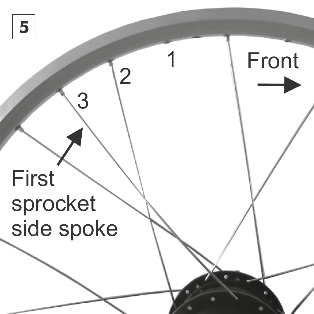
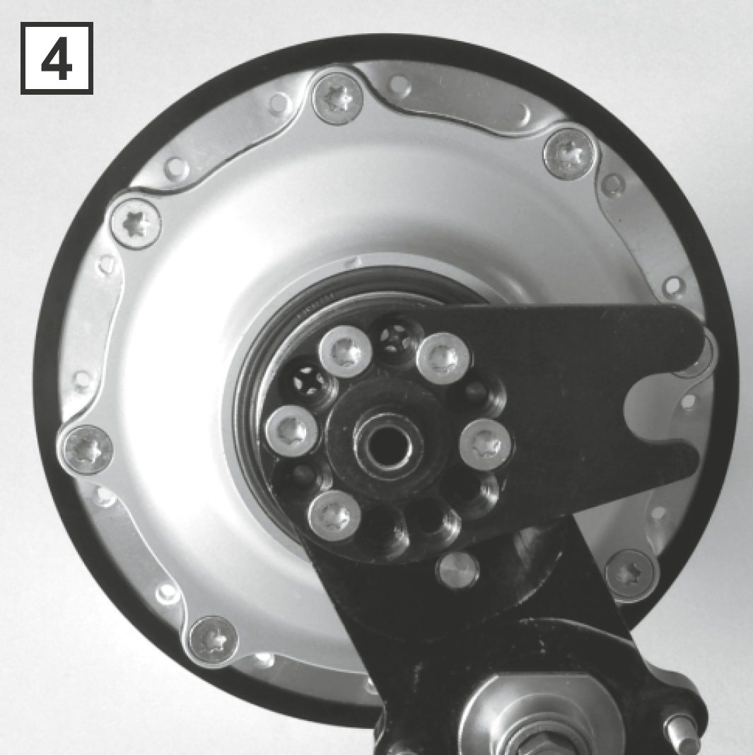
The valve hole is to be found opposite from a hubcap screw. The spoke hole of the flange opposite from this is where the first spoke on the sprocket side is to inserted from the inside (spoke head facing inwards). This spoke is to be inserted into the nipple hole of the rim that is 3 holes behind the valve hole. Lace all the remaining spokes in the same pattern as with the other side of the wheel (Fig. 3 and 4).
Rims with European spoke-hole pattern


Three holes (one hole) behind this first spoke is where the trailing spoke should be inserted, this spoke is to be inserted from the outside of the hub flange (spoke head facing outwards). This spoke is to be crossed over the first spoke and inserted into the nipple hole of the rim that is two holes before that of the first spoke.

The next trailing and leading spokes are laced into the rim in exactly the same way. The only difference being that they enter the hub flange two holes away from the last respective leading or trailing spoke, and that they enter the rim four holes away from the last respective spokes. Continue this process in pairs of leading and trailing spokes until all the spokes have been laced into the hubcap side of the wheel. Turn the wheel over.

The valve hole is to be found opposite from a hubcap screw. The spoke hole of the flange opposite from this is where the first spoke on the sprocket side is to inserted from the inside (spoke head facing inwards). This spoke is to be inserted into the nipple hole of the rim that is 3 holes behind the valve hole. Lace all the remaining spokes in the same pattern as with the other side of the wheel (Fig. 3 and 4).
Flange Support Rings
Flange Support Rings
Art.No. 8523 = 2x identical small rings Art.No. 8524 = 1x small ring, 1x large ring (groove - hub-cap side)
Fits all Rohloff SPEEDHUB 500/14 hubs. Mount to flange prior to lacing the wheel. Provides the flange with extra support in extreme/heavy duty (Tandem/Heavy duty touring, E-bike, Cargo, Cyclist 100kg) applications. Material: Anodized Black aluminum (20g).
Distinctive features
In der laufenden Serie wurden die Nabenflansche der SPEEDHUB verändert, so daß zwischen zwei unterschiedlichen Ausführungen unterschieden werden muß. Als Unterscheidungsmerkmal, welche Flanschringe benutzt werden müssen, dient der Schriftzug 'Made in Germany' auf dem Gehäuse der SPEEDHUB.


[Translate to en:] Bis zu den genannten SerienNr. sind beide Speichenflansche der SPEEDHUB gleich, so daß rechts und links zwei gleiche Flanschringe verwendet werden müssen = Art.Nr. 8523.
Bis/up to SerienNr. = Art.Nr. 8523
< 196922 si/silver - 32-Loch/hole
< 198454 si/silver - 36-Loch/hole
< 196521 sw/black - 36-Loch/hole
< 196713 sw/black - 32-Loch/hole
< 197520 rot/red - 32-Loch/hole
< 197980 rot/red - 36-Loch/hole